01
GRID CONNECTION
Sufficient grid capacity is not there, and will not be for years.
FLEETPOINT HD
Charging power comes from the module’s own energy storage, not from the grid connection.

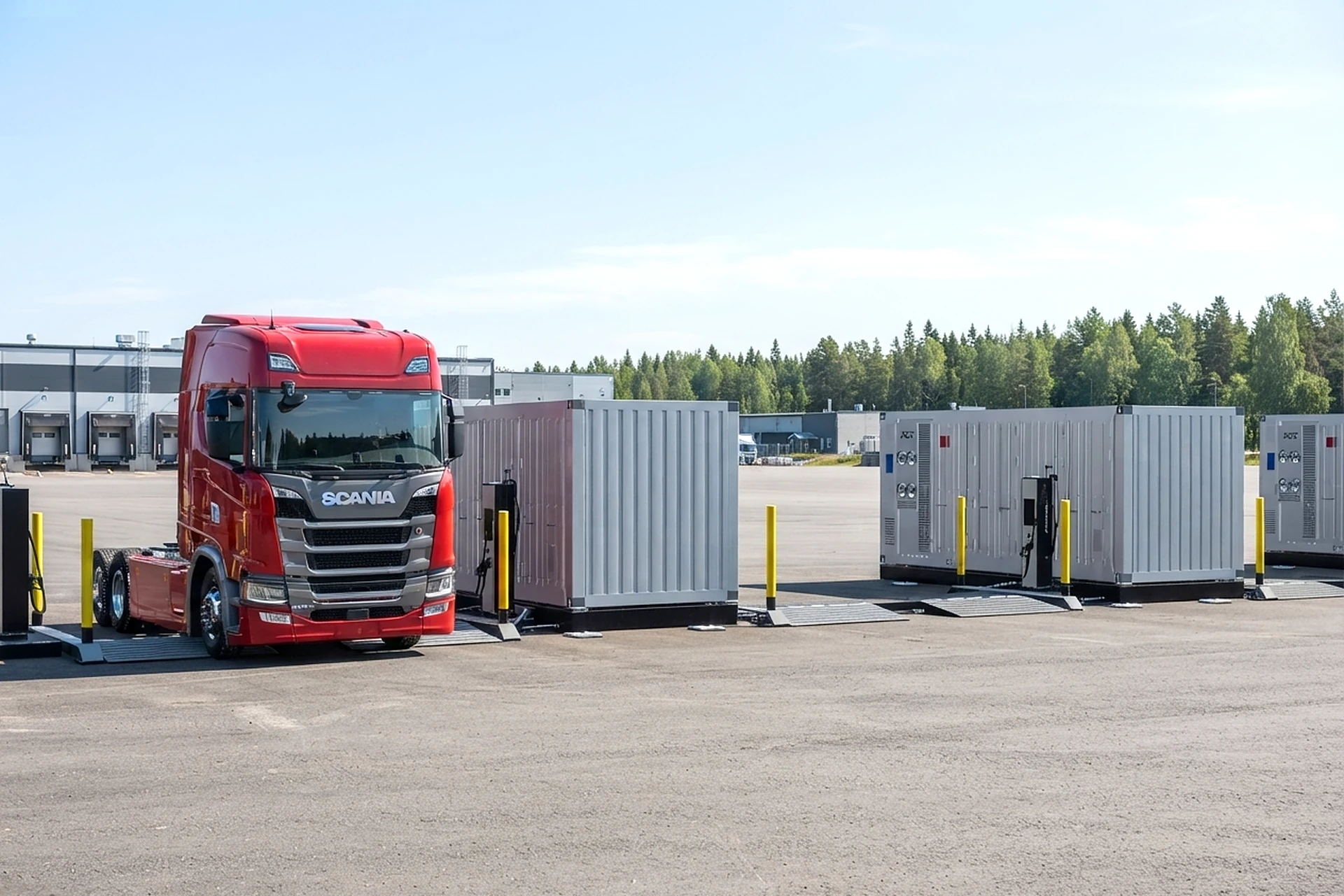
For every fleet – from vans to trucks and buses.
Modular high-power charging.
No construction project.
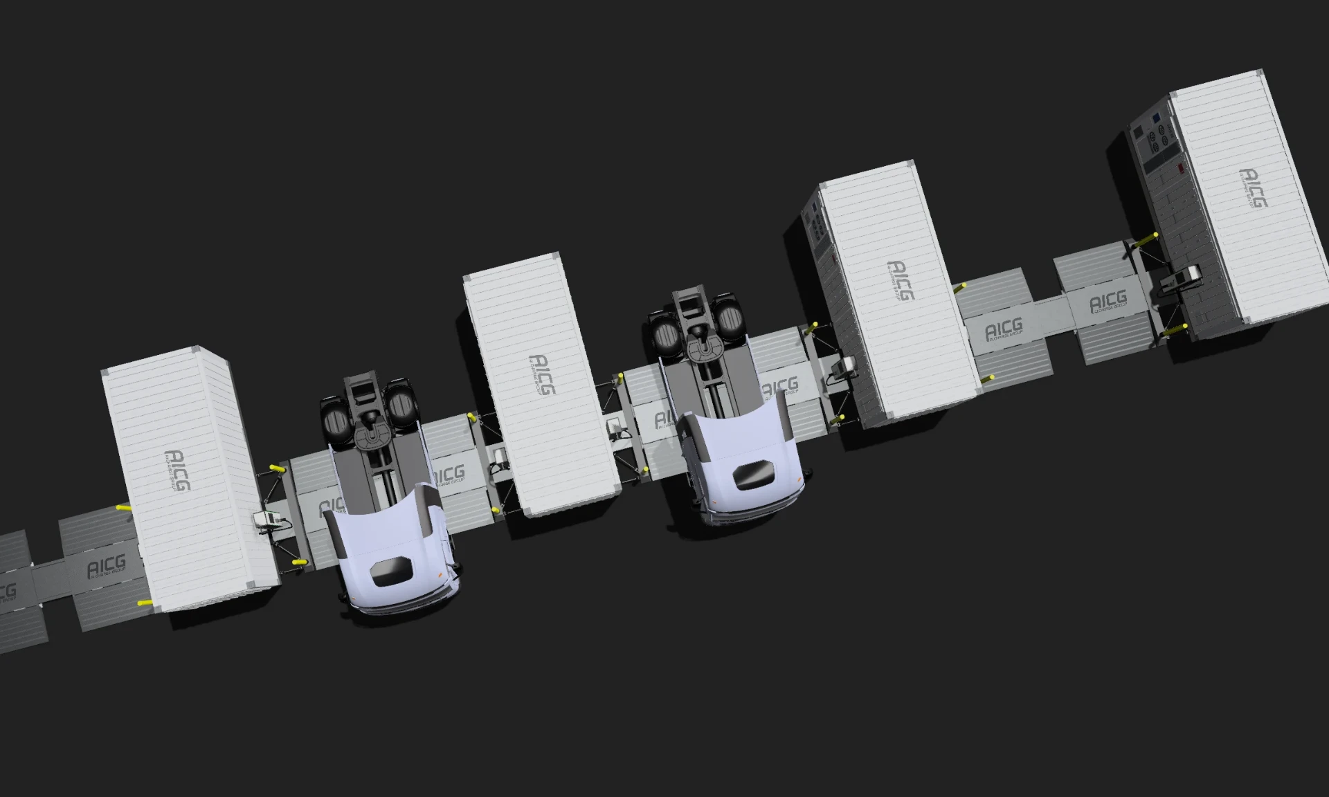
charging bays in one chain
cable channel, the backbone of the field
trenching, modules are set down on the yard
Sufficient grid capacity is not there, and will not be for years.
Charging power comes from the module’s own energy storage, not from the grid connection.
A fixed station takes too long, and the location decision is final.
Installed on the surface in a day. Relocated when needs change.
Equipment locked in concrete is a high-risk investment: its value is tied to one site and does not move when routes, premises or the fleet change.
Relocatable equipment holds its value, which makes it leasable. Leasing or capacity as a service. Scales up, scales down, relocates.
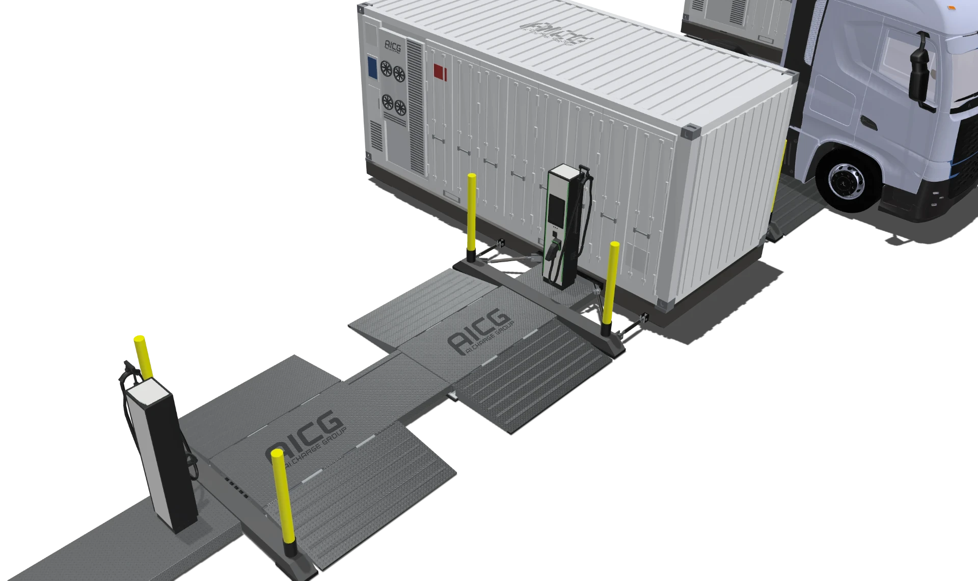
The module's own battery storage delivers full charging power directly to the vehicle, independent of the grid connection's momentary capacity. Chained modules can support one another: when charging demand calls for it, a loaded module's energy storage is boosted from another module.
Power electronics (PCS) and local energy management (EMS) in one unit. Power is routed to the satellite connected to the vehicle – one satellite delivers at a time. The power units of chained modules support one another within the field.
Double-sided DC charge point: a connector on both sides, so the bay can be entered from either direction and driven through without reversing. Sessions are prioritised by departure time and state of charge. The connector is CCS or MCS, depending on the power requirement.
The flat, surface-mounted power ribbon is the cable route between modules: the power cables are recessed in a low, protected channel on the flat-ribbon principle, with no trenching. The drive-over bridge protects the cabling and carries heavy-vehicle axle loads. The same ribbon chains the whole field into one system. Flood-water resistant.
A separate subframe allows installation on uneven ground and serves as a common mounting base for the modules. Moves with standard logistics, so deployment, expansion and relocation need no groundworks.
Fleetpoint UNIT, the stand-alone unit without drive-over bridge and chaining, is available separately as a product of its own for a single charging bay.
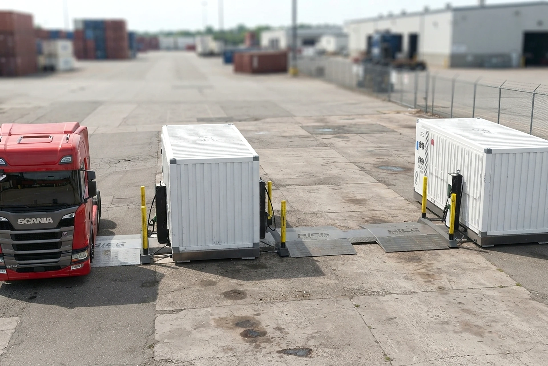
High-power charging on the existing yard, as it is.
charging bays per field
trenching, the yard stays in use
on-site installation
power as needed, MCS when required
Relocatable when routes, premises or plans change.
The charging power you need. A smaller grid connection. Storage buffers the peak: the grid sees a steady, capped load, the bays get full power.
≈1× grid → ≈3× charging power to vehicles
Cloud or controller may drop out, charging continues.
Example: 6 modules · 12 charging points · MWh-class buffer.
Rules · schedules · spot-price control · reporting · remote diagnostics.
Connection lost → site controller continues on last known limits.
Sessions · grid-limit supervision · prioritisation by departure time and SOC.
Control bus lost → the modules' power units support one another.
Grid-forming · protection.
Terminal traffic → fleet energy demand over time. Sizing: bays, power, storage, headroom for growth.
Modules on site in days. Digital plan · integrations · real-time monitoring.
AI-assisted operation driven by real-time demand. Actuals feed back into the plan.